Topic: Offset shift linkage--how?

I'm incredibly frustrated. I've been trying to fabricate a shift linkage setup for a 4 speed manual that will allow me to offset the shifter about 10" to the right using 2 universal joints angled at 27-degrees and some bronze bushings to act as guides. While I can get the swivel left and right to work, I can't get the forward and back to work I'm guessing because of the extreme (27 degree) angle of the forward U joint-- the forward steel shaft that connects to the tranny mounted shift coupler (which itself is a 3rd u joint of sorts--limited movement) keeps binding on the bronze guide bushing-- and it's not even hooked to the tranny yet.

Anyone have any ideas or more importantly links to photos of how this is done? I've been looking for something but really can't find anything and I'm becoming horribly frustrated.

I know I should probably go to the junk yards (especially since it's raining) and see how real cars do it, but unfortunately I'm house bound.

http://assets1.hubgarage.com/photos/0360/9703/ShifterLinkage_detail.jpg?1287351368

Re: Offset shift linkage--how?

Can you use cables instead?  Fabricate a mount on the trans for one end, and hook the other end to the shifter.

Dave Heinig - Schumacher Taxi Service
coROLLa - 2 time loser, RWB MR2 - 5 time loser
The Craptation - IOE WINNER! Lemons South Spring 2010
Crown Vic - Please God Don't Ever Make Me Go Through That Again

Re: Offset shift linkage--how?

Unfortunately, I don't think so. There are springs and ball detents to overcome in the tranny internals and it's a push/pull for first second, then a rotation to move shift gates, then a push/pull for 3/4, then a rotation to move into reverse gate, then another pull (but who needs reverse, right?) The ball detents are at each gear locking the shift fork into position as well as the syncro hubs into the gear.

However, if you can think of a way to do cables, I'm open to it.

4 (edited by Spank 2010-10-17 02:34 PM)

Re: Offset shift linkage--how?

Here's the layout before I added the steady brackets and the bronze guide bushings.

http://assets1.hubgarage.com/photos/0360/9899/1010101711_detail.jpg?1287354381

Re: Offset shift linkage--how?

Hmmm. wonder if this might help alleviate some of the binding that I'm experiencing at the end bushing...

http://bearingsdirect.com/store/index.p … amp;p=3812

http://bearingsdirect.com/store/images/products/detail_3812_LM-sml.gif

6 (edited by st_rage 2010-10-17 04:46 PM)

Re: Offset shift linkage--how?

My intuition is that you won't get that setup to work.  When you push on the shifter it wants to twist the intermediate link and will create a large side load on the bushing.  The large side load will bind it up.   The high angle is what's causing the binding.  At a minimum you need to support the straight pieces with linear bearings as close the to u-joints as possible and have them rigidly mounted.

It would help if you can eliminate one of the u-joints and reduce the angle.  Then you'd only need  bushings at the transmission end to keep things straight.

You might also consider bending the shift lever to allow the shifter to be closer to the centerline to further reduce the angle.

Our Lady of Perpetual Downforce
http://www.perpetualdownforce.com/

Re: Offset shift linkage--how?

Hey Spank, the ASP used craftsman 3/8" u-joints and heims-joints about 4" either side of each joint to get the shift from the rear to the driver. It was convoluted, but it worked.

I was thinking of doing a mod from a boat-steering or shifting cable - one cable to do the twist and the other to do the in-out.

I think in the Apollo's case you could do a U-joint and rod for the in-out and do the rotate with a  boat steering or shift cable - the advantage of the cable is that you can mount the arm/lever/cam on the in/out shaft and mount the cable-housing holder 4-6" away and not have to worry about the sliding motion transfer and alignment...

--as in, put a lever on the output of the trans, mount a cable at 90 degrees to car centerline - run the rod pretty much like you have it and then either put the cable to the bottom of the shifter ball or make a lever just like you did on the other end (the latter should be easier with the std Rod-x box than the former)

Luck, wish I was there to cobble that one together w/you.

8 (edited by Spank 2010-10-17 11:06 PM)

Re: Offset shift linkage--how?

I guess I owe Dave an apology-- I didn't really understand/know what you meant by cable shifting. I think I'm kinda getting it a little bit now. Never seen one before... Better find a way to go to pick-a-part and see how that stuff works.

Appreciate the ideas, everyone.

Here's a pic of the failed attempt:

http://assets0.hubgarage.com/photos/0361/2220/ShiftLinkage3_detail.jpg?1287373804

The length of the forward rod is pretty short and there's not many options for where to put the support bushing for that shaft. It's about as close to the u joint as the required shifter movement will allow. I'm going to try to relax the angles a tiny bit and try some linear bearings and maybe a guide plate up against the area where the U-joint wants to thrust to hopefully help direct it forward. FWIW, the throttle pedal and hence the ball of the driver's foot is just above the rearward frame cross brace.

If someone has a suggestion for a vehicle that uses a cable setup that I should go look for and consider copying, I'm all ears.

Re: Offset shift linkage--how?

Another option that I have only thought through but not sketched out yet (I have no CAD software - so bar napkins are my usual level of sophistication for tech drawings) is to put the stock shifter on the trans wherever it goes. Then build a median 'shifter relay' directly forward (i.e. straight forward from the 3-4 shift line) that is a rod with the same height as the stock shifter rod and the same diameter - the pivot for this forward displaced 'relay' is in the same exact horizontal plane as the stock shifter. Then build a third device, we'll call it a 'proxy shifter' with the pivot in the same plane as the other two pivots, and the same rod length/diamter as the other two, this one located 90 degrees off of the axis of the stock shifter to the 'shifter relay'.

Now you have three identical linkages (not hooked to each other yet, that comes next) that all have the same height/diameter lever and pivot on the same horizontal plane. Stock one is where ever it has to be, relay is directly in front of the stock one, and proxy shifter is directly to the side of the relay (all assuming your trans is too far back but basically any displacement can be addressed by two right angles as long as you can keep everything in the same plane).

Now go find a heim joint that fits the rods (as far up as possible to allow for all the errors in fabrication, and you actually want to buy all the rods / modify them to fit a size you can get heim joints for in planning - but you knew that) and buy four of them. You'll cut one of them and weld part of it to make a right angle fitting for the relay rod with it (you end up with a stock heim joint, with an extra female thread portion 90 degress offset, and in the same horizontal plane as the original one). Then you'll mount that to the relay rod at height x up from pivot, mount one of the unmodified ones to the stock shifter x up from pivot, then the last unmodified one to the shifter proxy at height x up from pivot.  Then use tie rods or something similarly crappy to tie them together (start with the lengths between the pivots, and I imagine you'll end up fiddling with it to get it to make it shift). You'll need bracing between the two right angle tie rods - probably a lot of it, and reverse may not be manageable with this goofy linkage.

Caveat: I haven't built this yet, so if it doesn't work for some glaringly obvious (or otherwise)reasons, you should have known better than to listen to some guy on the internet.  If it does work, I'd appreciate pictures of it completed...

Good luck.

Re: Offset shift linkage--how?

If you want to play with cable shifting go to the junk yard/pick and Pull and find a 1985-89 MR2
The cable shift assembly is totally self contained it has two 3' cables a low profile shifter box and shifter all in one. Cheep and a possible fix.

Team: V-Ram/Altamont Team: Knights of the Round Track/Reno/Buttonwillow/Thunderhill Team: Death Mobile/Sears 2010/Thunderhill/ChumpCar  Spokane/ MSR Houston/Buttonwillow/Sears. MRolla Project /Reno
http://stickfigureracing.blogspot.com/

Re: Offset shift linkage--how?

If you can't find that, there should also be at least 1 SHO in the junkyard. The 1st gens have a pretty versatile cable setup.

The Charnal House Geo MetSHO: Turning less laps than a regular Metro, the hard way!

1969 Subaru 360

Re: Offset shift linkage--how?

~damn, forgot about the Mr. two - I'll be off to PnP again Tues - there's one in the next closer pnp to me - wasn't planning on going there but could if you wanted, then I'd mail it off.

Re: Offset shift linkage--how?

I think most FWD cars have a cable shifter.  They use two cables, one for fore-aft movement, another for left-right movement.  Probably cheaper and easier to find one from a common, readily available car like a Focus or something vs. an MR2.  (unless you need the potentially longer cables from the MR2.... but even FWD cables are likely to be 5-6 feet long)

Lemons South 2008 - Fail, Lemons South Spring 2009 - Fail, Lemons Detroit(ish) 2008 - Fail, Lemons South Fall 2009 - Fail, Lamest Day 2009 - Fail, Miami 2010 (Chump) - 2nd!, Sebring 2010 (Chump) - Fail, Cuba 2010 - Crew Chief, Roebling 2011 (Chump) - 8th!, Sebring 2011(Chump) - 19th!

14 (edited by DaveH 2010-10-18 12:24 PM)

Re: Offset shift linkage--how?

The only problem with the MR2 cables is they come out of the back of the shifter.  You'd lose most of the extra length looping them around to the front.  I'd look for a FWD Toyota or a FWD GM.  I think they mostly used cable-shift. 

Also, now that I understand how it works, your problem is that the middle rod is creating thrust to the left and right on the U-joints, binding the forward and aft rods.  If you put a bushing between a pair of flanges on the middle rod, and then had the bushing on a slider that restricted the linear movement of the rod to only the front/rear axis, it would probably work a lot better.  That would be fairly difficult to machine though.  Even better would be two bushings that were locked together at the correct angle.

Dave Heinig - Schumacher Taxi Service
coROLLa - 2 time loser, RWB MR2 - 5 time loser
The Craptation - IOE WINNER! Lemons South Spring 2010
Crown Vic - Please God Don't Ever Make Me Go Through That Again

Re: Offset shift linkage--how?

You could try adding a second bushing on each of your two short sections.

Your problem as you sort of talked about is the linkage is twisting and binding in the 1 bushing. When you push forward (or back) the motion is transmitted along the shaft (straight line), and then to the universal. But the universal, operating at an angle converts the linear F-B motion into a motion that is now 27 degrees off axis. When it does that there is a corresponding reaction in the opposite direction. That reactionary force rotates the first rod counter clockwise. That 1 binds up the rod in the bushing, and 2 reduces the amount of force getting transmitted to the next universal, where it happens again. So with all the loss of force, you get no movement on the other end. All the force applied gets turned into rotational forces in the universals, which just flex because that's what they do, and the result is no movement at the tranny.

two bushings on each rod will limit the amount of rotation to near zero and should allow more force to be translated. You'll still have some slop in the universals which will dissipate some of the force, but it should work.

A better linkage would use one rod for the front to back with pivot linkages on each end (essentially what the shifter is, pivot in the middle). then you need a second bell crank to transmit the side to side.

Dudes Ex Machina: https://www.facebook.com/dudesexmachina

?Everyone who has ever built anywhere a 'new heaven' first found the power thereto in his own hell- Frederick Nietzsche

Re: Offset shift linkage--how?

DaveH wrote:

The only problem with the MR2 cables is they come out of the back of the shifter.  You'd lose most of the extra length looping them around to the front.  I'd look for a FWD Toyota or a FWD GM.  I think they mostly used cable-shift. 

Also, now that I understand how it works, your problem is that the middle rod is creating thrust to the left and right on the U-joints, binding the forward and aft rods.  If you put a bushing between a pair of flanges on the middle rod, and then had the bushing on a slider that restricted the linear movement of the rod to only the front/rear axis, it would probably work a lot better.  That would be fairly difficult to machine though.  Even better would be two bushings that were locked together at the correct angle.

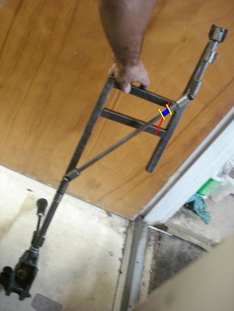
This is sort of what I was talking about - the red is the slider, the yellow are the flanges welded to the shaft and the blue is the bushing:

http://farm5.static.flickr.com/4126/5094695232_604d5c9de8.jpg

Dave Heinig - Schumacher Taxi Service
coROLLa - 2 time loser, RWB MR2 - 5 time loser
The Craptation - IOE WINNER! Lemons South Spring 2010
Crown Vic - Please God Don't Ever Make Me Go Through That Again

Re: Offset shift linkage--how?

am i missing something? why cant it be a solid piece of steel rod (ya know, sans u-joints)?

all the good Hondas are link shift, and they are a single piece of metal.

cant you just bend some rebar?

Yee-Haw 2010 "Most Heroic Fix" & "I Got Screwed" -2 trophies for 1 lap, but I took checkered on my lap.
Gator-O-Rama 2012 "Organizers Choice" -2 laps 1 trophy, but i still finished ahead of an E30
Yee-Haw 2013 No trophy -26 laps, I think I see a pattern here
Gator-O-Rama 2014 "Waiting for the Last Minute Call from the Governor Award" -who's counting? John

Re: Offset shift linkage--how?

It looks like a solid bar won't work because this is running under the driver's feet?!  A solid, bent bar would probably require 8-12" of swing with this amount of bend & Spank needs to keep everything tight to the floor!?

The setup you have should work if you can get rid of the rods at the shifter & the trans.... If you could put the universals directly on the shifter & trans with one rod in between, you've got a chance.

Most Formula Vees have a similar set-up, but you have to keep everything in-line to retain the fore-aft rigidity.... otherwise, you might as well be pushing a rope.  Retro-fitted cables would work, but I gotta believe a good solid linkage would be more trustworthy.

Eric

Re: Offset shift linkage--how?

That diagonal piece doesn't need to push in and out-- it's only supposed to (in my eyes) say in the same plane and move fore/aft-- so the two sections of lengthwise rods move in and out and the diagonal just moves front to back. Someone on the team pointed out to me in order for it to work the two forward facing rods need to be in the same alignment: traveling in the same trajectory just split into to different parallel planes. I think the forward is angled more than the rearward one which is another reason there is binding.

I'm not giving up on this design quite yet. Will play a bit and see what happens.

Appreciate all of the advice everyone and will go the cable route if this one ends up sailing out into the middle of the street boomerang style about 3am some time in the near future...

Re: Offset shift linkage--how?

The offset is the problem, it makes everything bind. I'm sure it could be made to work, but at what cost etc?

Another good candidate for cable shifter stuff: PT Cruisers.  I think Neons used the same setup.

Philosophy of life: old age and treachery will ALWAYS overcome youth, enthusiasm and cash. General smartass know it all beer swilling ne'er do well. Avoid eye contact with this person, best avoided completely. 2008 Animal House Racing CMP 'Most Likely To Leave In An Ambulance' 2009 Blind Rodent Racing CMP 2010 Team Galileo CMP 2011 Roundhouse Kick Racing CMP 2012 Road Kill Grill Racing CMP (x2)

Re: Offset shift linkage--how?

DaveH wrote:

The only problem with the MR2 cables is they come out of the back of the shifter.  You'd lose most of the extra length looping them around to the front.  I'd look for a FWD Toyota or a FWD GM.  I think they mostly used cable-shift.

Well, you could make the MR2 cables go forward instead of backward very easy. Just a matter of removing a couple bolts and flipping the cables. But going with a FWD Toyota would probably be a better idea cause then you don't have to do even that.

Pat Mulry, TARP Racing #67

Mandatory disclaimer: all opinions expressed are mine alone & not those of 24HOL, its mgmt, sponsors, etc.

Re: Offset shift linkage--how?

It looks like the transmission in question uses a single rod for shift control, while the cable shift stuff that I have seen (mostly Chrysler) uses two cables: one for select (fore/aft) and one for crossover (right/left).  I don't see how you could adapt a two-cable system to a transmission that was designed for a single rod without some precise fabrication.  A crossover lever on the outside of the transmission - to translate the push/pull motion of the crossover cable to a twisting motion of the transmission rod - would have to be precisely built and well lubricated.

Team Co-Craptain, Los Cerdos Voladores
Plymouth Neon
Yeah, we're horrible...but we're LEAST Horrible

Re: Offset shift linkage--how?

Extend the stock shift rod straight back under the seat. Build a second shifter offset to the right, where you want it. Mount it on a gimball and use heim joints to transfer the movements.

A picture would be worth so many words right now, but I'd have to do some drawing.

Re: Offset shift linkage--how?

remove both the support closest to the transmission, and the slider support. mount the transmission side u-joint as close to the linkage attachment as possible, this'll decrease the angle you're putting on that indermediate and should remove any binding.... should but it's only a couple cuts away, so worth trying. it's a common setup on Formula Vee and other formula style race cars that use H-pattern shifers. however the angle i'm looking at on the Vee is only about 10 or 15 degrees, so idk how well 20-27 degrees will work (20 being a guesstimate of if you were to move the U joint to the trans instead of the firewall. you can also mount the shifter itself cockeyed to decrease that angle, but give your drivers lots and lots of time to figure it out...