Topic: Anyone to waste time on DIY engine control unit?
Looking for someone to join me in wasting time by making an engine control unit from scratch. I have wasted enough time to have a working prototype, so please excuse my sales pitch in a non-Lemons language, I am pasting from another site:
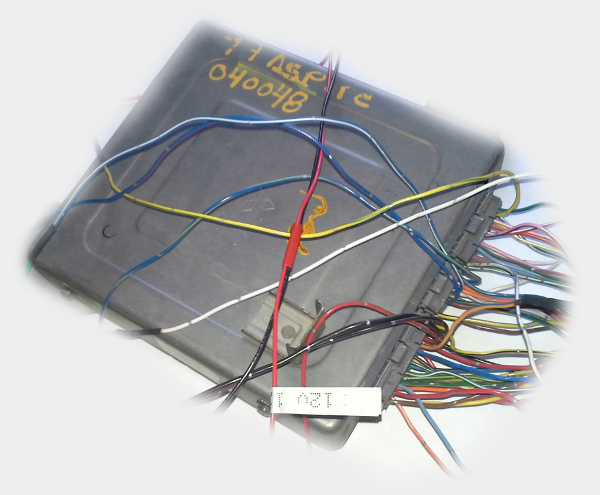
In this article I will explain how I hacked into my car harness in order to read current RPM. This approach is not universal and there are no guarantees - this article only applies to my car and you should not attempt doing anything like that to yours.
A bit of technical background first: the car I have hacked was sold in US as Ford Aspire, it was made in South Korea and it's Mazda design with some Mitsubishi components. Not your average F150 exactly ![]() This car uses Hall effect crankshaft position sensors (no idea how that works). So I could have used the same approach for something like Mazda Protege or even a Miata from the 90's - the younger cars would have sensors based on Variable reluctance and that would be a different story.
This car uses Hall effect crankshaft position sensors (no idea how that works). So I could have used the same approach for something like Mazda Protege or even a Miata from the 90's - the younger cars would have sensors based on Variable reluctance and that would be a different story.
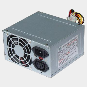
When I open the hood, I see a distributor like the one on the picture: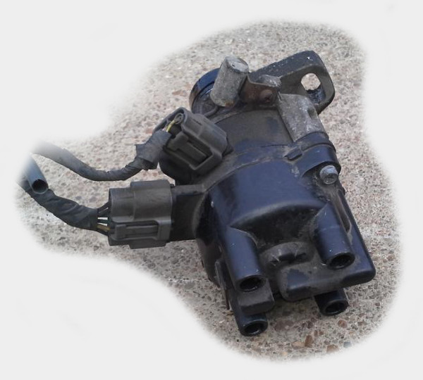
If I would have decided to break this distributor and look inside, I would see something like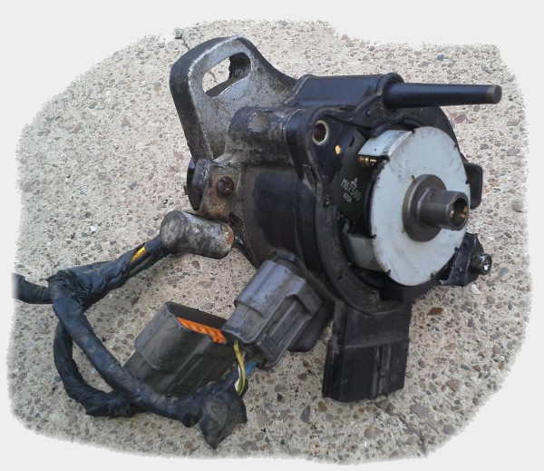
That tin wheel spins with the crankshaft and that's what make the CKP signal. If I would keep taking it apart, I would see the actual sensors and the other wheel - the smaller wheel is in charge of CID signal. 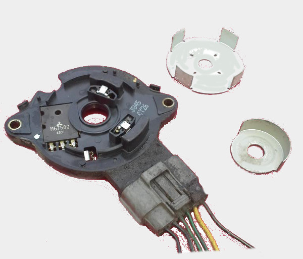
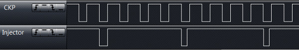
Does not really matter what CKP and CID signals are. We only care that even while the car has a 12 volts battery, most of the sensors and the stock ECU run on 5 volts. Somewhere in my harness where are two 5 volts wave signals which look like this: 
That's it. We can wire this signal right into the any 5v tolerant microcontroller. Just to be a bit safer, we will put a 1n4001 diode between the harness and the microcontroller.
So, let's get something done. Let's take a STM32F4DISCOVERY dev board - that's a $15 board based on some stm32f4 microcontroller running at 168MHz. 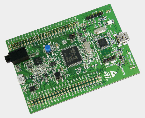
That's actually a lot of cheap computation power.
As is, microcontrollers are not exactly super friendly - ChibiOS/RT would help us, we will let it take care of the the lower level. We will use serial-over-usb to output data - so, mini-usb cable would be used to flash & power the board and the micro-usb cable would be used for serial. If you made it to here you probably know what serial is.
It's not much code, it's quite self-explanatory:
volatile int rpm = 0;
int lastInputEventTime = -10 * CH_FREQUENCY;

void icuWidthCallback(ICUDriver *driver) {
    int now = chTimeNow();
    int diff = now - lastInputEventTime;
    rpm = 60000 * TICKS_IN_MS * 2 / 4 / diff;
    lastInputEventTime = now;
}

ICUConfig wave_icucfg = { ICU_INPUT_ACTIVE_LOW, 100000, icuWidthCallback, NULL };

int main(void) {
    halInit();
    chSysInit();

    // this thread would blink one of the LEDs, that would look cool
    chThdCreateStatic(blinkingThreadStack, sizeof(blinkingThreadStack), NORMALPRIO, blinkingThread, NULL);

    // serial-over-usb initialization
    usb_serial_start();

    // configure input signal pin
    palSetPadMode(CRANK_INPUT_PORT, CRANK_INPUT_PIN, PAL_MODE_ALTERNATE(GPIO_AF_TIM2));

    // start input capture - we will handle input events and calculate RPM based on the timestamps
    icuStart(&CRANK_DRIVER, &wave_icucfg);
    icuEnable(&CRANK_DRIVER);

    while (TRUE) {
        // RPM value is updated by the input event handler
        chprintf(&SDU1, "rpm: %d\r\n", rpm);
        chThdSleep(100);
    }

    return 0;
}
It really isn't that hard, right?
I've got the software side of things covered and forced myself to figure out enough electronics, And the whole effort is absolutely pointless anyway, so why not join me?
PS: I think this is more 'Tech' then 'Human Resources'?